
Environnement Sensor
Instructions :
For our 3rd-year BUT project, which takes place throughout the year, we are tasked with developing an environmental monitoring system for a room.
This system must be able to measure and communicate information about various environmental parameters to a user via a communication system. The system must be autonomous, cost-effective, and easy to install and maintain. It must include sensors to measure temperature, CO2 levels, as well as the status of the lighting and windows in the room. Furthermore, the system must have an attractive design for users.


Functional Analysis:
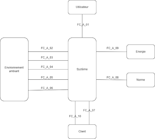
Octopus diagram of the system in nominal operation:
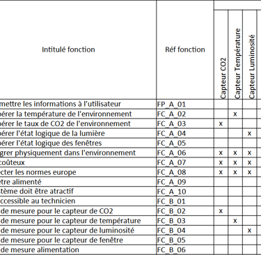
The first step in a project is to conduct a functional analysis. This will be very useful, initially, for drafting the requirements specification (cahier des charges). It will then be used for writing and defining the decision matrices.
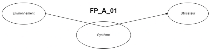
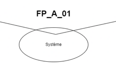
FP_A_01 : Transmettre les informations à l'utilisateur
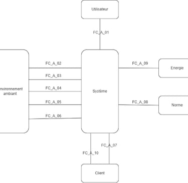
Following this, we produce two "octopus" diagrams. The first one is used to describe the nominal operation of the system. The second one is used to describe the system in maintenance mode.
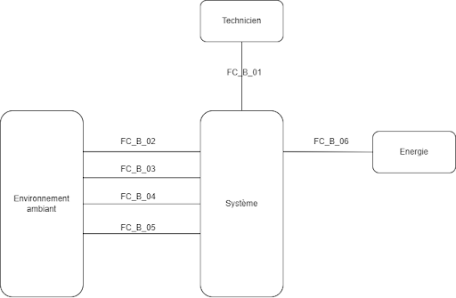
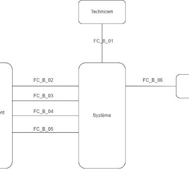
Diagramme pieuvre du système en fonctionnement maintenance
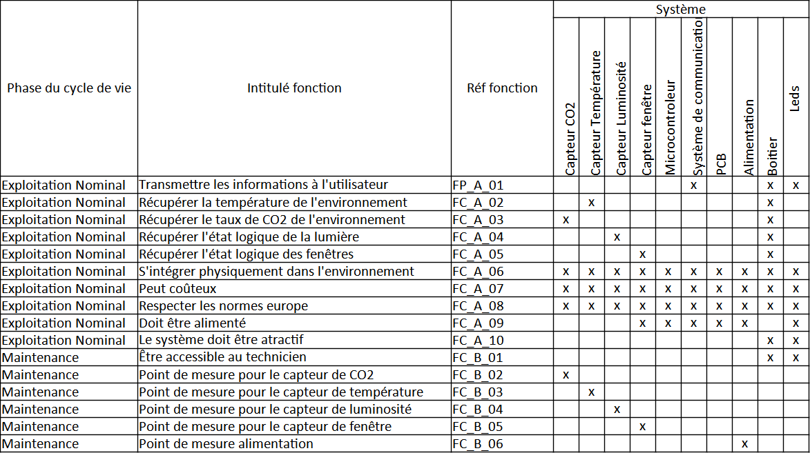
Organic Allocation of Functions
To transmit data from the various sensors to the user, we decided to use the low-power wireless communication technology "LoRa", on the recommendation of Mr. DUVIELBOURG. This technology is commonly used in Internet of Things (IoT) applications and could prove particularly effective for our environmental monitoring system.
First, we will study the operation of a LoRa network. For this, we are using "The Things Network" and a Gateway of the same brand. To run some tests, we were loaned an Arduino MKR WAN 1310 microcontroller, with an MKR ENV shield, which includes sensors for pressure, temperature, humidity, and light.
We will initially try to send a message via the LoRa network. The communication class will be Class A; the system will spend most of its time in sleep mode (waiting) and will communicate its information every 30 seconds.
We managed quite easily to send and read the temperature and humidity sensor information in "The Things Network" terminal. However, we are encountering a problem when sending data using interrupts; the microcontroller freezes, and we receive no information on "The Things Network".
This is why, in addition to the price, we will not be able to keep this board for subsequent use.
Search for Solutions
Communication System
Component Selection
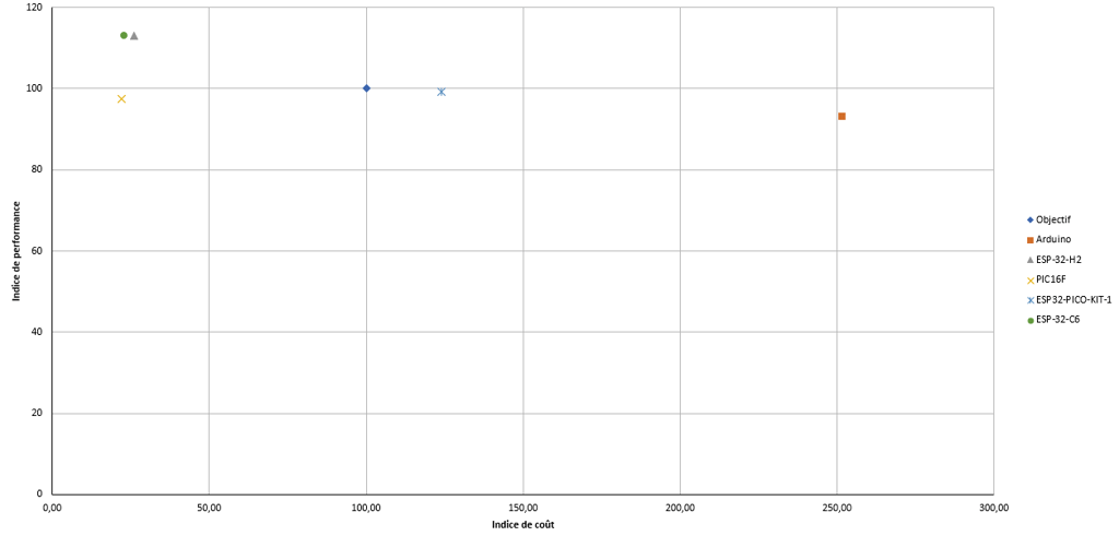
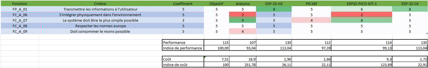
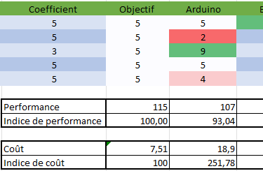
All component choices are described in the document A_AF_SAE5. We use decision matrices to compare several solutions for a given requirement.
For the microcontroller and LoRa communication selection, the initial choice was to use a microcontroller with integrated LoRa WAN. This would have been more efficient and faster than implementing a LoRa chip on a separate microcontroller. However, we realized that it is difficult to find microcontrollers with integrated LoRa chips at a reasonable price.
Our choice, therefore, turned to the PIC16F microcontroller and the Seeeduino LoRa-E5-HF, which were also chosen by other groups.
The logic is as follows: the PIC is the central chip; it manages the communication between the Seeeduino (outputs) and the sensors (inputs). Communication between the PIC and the Seeeduino will be done via UART (RX/TX). This resolves the issue of sending information using interrupts. The PIC16F microcontroller has an internal comparator.
We selected the CO2 sensor from Scio science, a company that builds scientific sensors. The datasheet is complete, and communication will be via I2C.
The temperature sensor is an LMT887. It is a commonly used sensor, stock levels are high, and the sensor is already linearized with the formula to obtain the temperature.
The light sensor [Note: This might be the window sensor] will be an NO (Normally Open) or NC (Normally Closed) switch.
For the lamp status sensor, we will use a photodiode, which will give us a voltage based on the room's light. A trigger threshold must then be set to have a logical sensor rather than an analog one (necessary for triggering interrupts later). For this, we are using an LM393 comparator with a pull-up resistor.
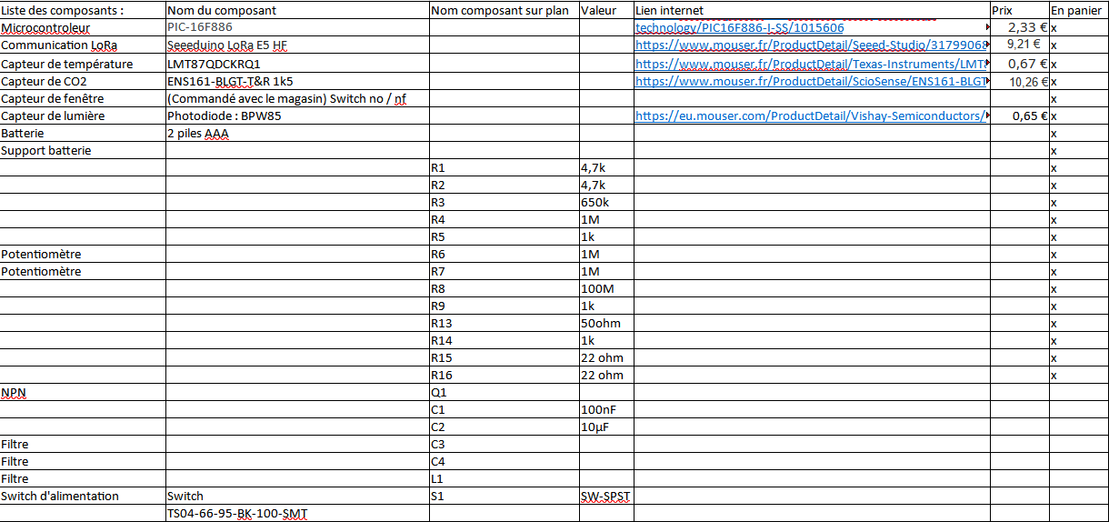
Based on all these choices, we will create the "Bill_Of_Materials" file, which will contain all the part numbers (references) for the components that will be included in the system.
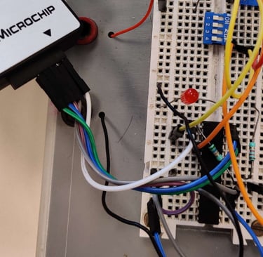
To de-risk the component selection and at the client's request, we are testing the system's operation and the program on a breadboard.
We are simulating the logical sensors with buttons and the analog sensors with potentiometers in order to verify/de-risk our program's logic.
We are encountering a problem when sending data using interrupts. When an interrupt is used to send information, the microcontroller freezes, and we receive no information on TheThingsNetwork.
Tests on Breadboard

Hardware Change
It was decided to change boards and to use the LoRa module from Seeeduino, controlled by a PIC16F microcontroller.
The logic is as follows: the PIC is the central chip; it manages the communication between the Seeeduino (outputs) and the sensors (inputs). Communication between the PIC and the Seeeduino will be done via UART (RX/TX). This resolves the problem of sending information with interrupts.
The PIC16F microcontroller has an internal comparator. According to our professor, the PIC16F also has an internal RTC (Real-Time Clock). We later realized that it is a timer and not an RTC.
Advantages:
Cost savings (No duplication of functions)
Disadvantages:
More complicated to implement (The function is more complicated to use than an external RTC)
The program's operating logic will therefore have to change.
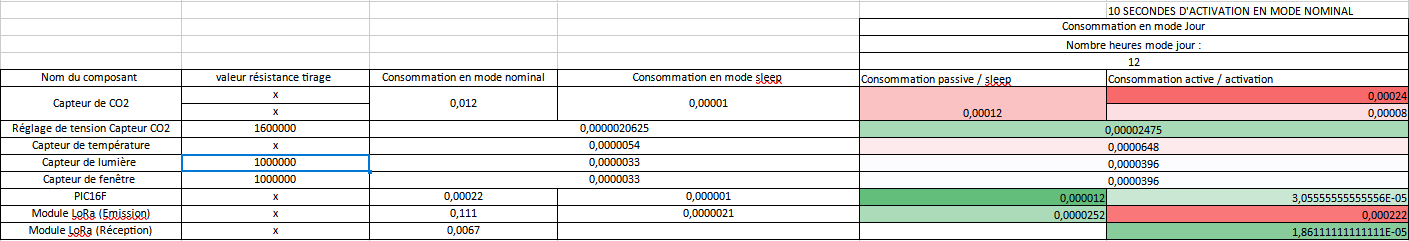
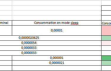
System Consumption
The objective now is to determine the board's consumption in order to size the battery. When selecting components, we minimized consumption as much as possible.
After calculating the consumption estimate, we can conclude that with 2 AAA batteries of 1500 mAh, and an operating mode of 72 measurements per day (maximum number of measurements), we can achieve 7.4 years of autonomy.
We have found all our solutions; we can now produce the PCB.
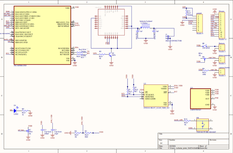
The PCB CAD (Computer-Aided Design) will be carried out using Altium Designer software. First, we create the functional part of the schematic. In "Schematic" mode, we place the components we have selected. Next, we made the connections between the components, using the datasheet for each component as well as the tests we performed on the breadboard.
PCB Design
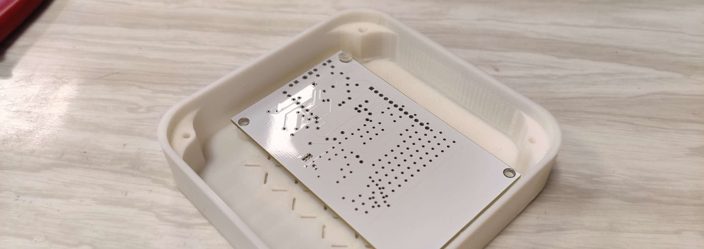
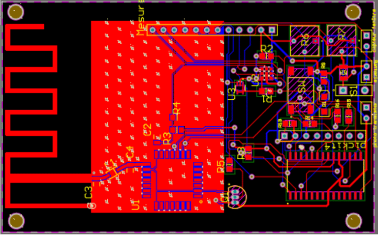
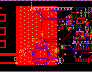
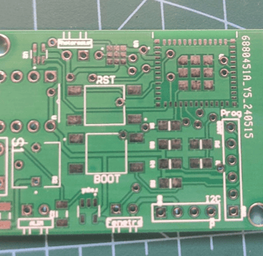
When the schematic is finished, we can finally begin the PCB layout. To do this, we started by choosing arbitrary dimensions to begin placing components on the PCB. It is a two-layer PCB; in our case, we positioned components only on the top layer, with just a ground plane on the bottom. We created a patch antenna dimensioned for 868MHz, the LoRa communication frequency. We also included test points on the PCB to make future maintenance easier. We thus obtained a PCB that looks like this:
We then exported this file in Gerber format and ordered 5 PCBs from JLCPCB to provide a functional prototype.
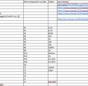
I produced a list of components to order to complete the project.
Bill of Material
In parallel with the PCB design, I will create the program's logic. The objective is to design an algorithm that is easily modifiable. We are programming on a PIC16F; the language used will be C.
For value acquisition, the following functions will be used:
int getTemperature()
int getCO2()
bool getLight()
bool getWindow()
The "day mode" schedule is adjustable according to the user's choice.
Program Design
Day Mode
Night Mode
Temperature Sensor
It measures the temperature every 30 minutes.
Window Sensor
Inactive in day mode.
Light Sensor
Inactive in day mode.
CO2 Sensor
It measures CO2 every 30 minutes. If it exceeds a certain threshold, the time is reduced, and it switches to 3 measurements spaced 10 minutes apart, until the value falls below the threshold.
Window Sensor
As soon as it changes to night mode, acquisition of the windows' status. Then, as soon as there is a state change (interrupt), acquisition of the windows' status.
Light Sensor
As soon as it changes to night mode, acquisition of the light's status. Then, as soon as there is a state change (interrupt), acquisition of the light's status.
Temperature Sensor
Inactive in night mode.
CO2 Sensor
Inactive in night mode.
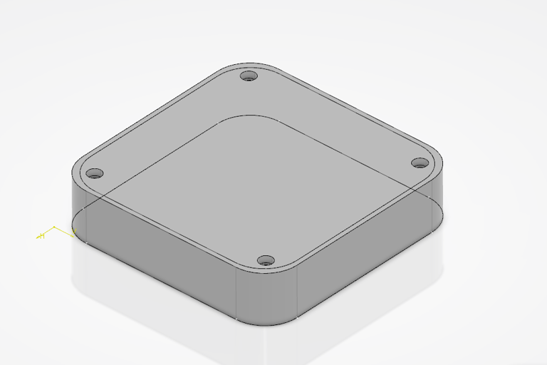
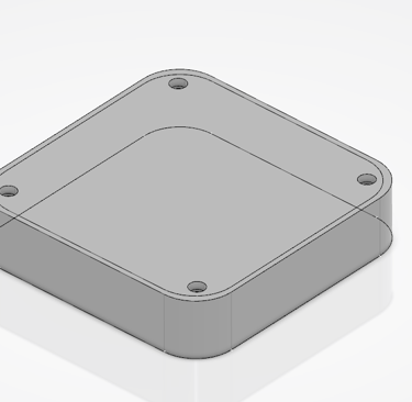
Enclosure CAD (Case Design)
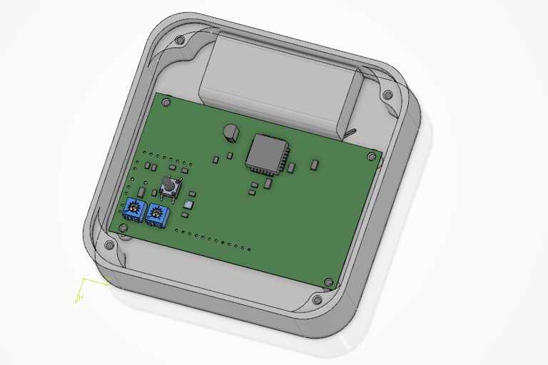
The enclosure CAD will be carried out using the 3D Experience software. First, I will import the PCB as a 3D file.
This way, I can see the position of the sensors, holes, and connectors.

3D Print
PCB Tests
We started by soldering the CO2 sensor using the (reflow) oven. Then, we soldered the rest of the components with a soldering iron.
We found better connectors than those initially planned. We therefore wired the connectors and made the cables used to connect the main enclosure and the auxiliary sensors.
Once all the components were soldered, we needed to blink the test LED to verify if the microcontroller programs correctly. After a few problems with the programmer, we successfully managed to blink the LED.
Since we had previously written a functional program for the comparator that worked on the breadboard, we decided to test this program first. However, it did not work as expected.
We then realized there was a wiring error with the R7 potentiometer. The GND and ref_lum were inverted (swapped). This will need to be modified in the next version of the PCB.
In the meantime, we cut the trace and added a wire in its place to verify the comparator's operation.
However, the system still does not work as expected; there is a short circuit on the temperature sensor or the particle sensor. To correct this short circuit, we had to cut the power trace for both sensors. This makes them inoperable.
Comparator Error
After resolving the PCB wiring problems, we tried again to get the comparator working in order to generate an interruption. We succeeded in making the comparator work as it did in our previous tests. At this stage, we attempted to implement the interruption.
The program is simple: when a state change occurs, it triggers the interruption and changes the LED's state. However, this does not work. To clarify this situation, we measured the comparator's output and found that it is not digital. The comparator oscillates slightly, which prevents the interruption from triggering.
System Change Study
At this point in the project, we are reaching a new milestone. We have 2 weeks left to get the system working. We still have all the following parts to program and test:
Read a logical input
Send information via LoRa
Receive information via LoRa
Get the CO2 sensor working
Get the temperature sensor working
Get the light status sensor working
Get the window status sensor working
Get the interrupts working
Get the timer working
Get the main program working
Power via battery
Program the maintenance function
Program the database
We are therefore questioning the feasibility of the project on time, knowing that we will also have to produce all the documentation related to the project.
The delay incurred is due to several problems:
Microcontroller :
The choice of the PIC16F was a bad one; it is a very low-level and not very accessible microcontroller. While the microcontroller meets all the requirements and has all the requested features according to the specifications, even just turning on an LED is much more complex than with other microcontrollers.
Currently, we have managed to turn an LED on and off and get the comparator working. In 3 weeks, I seriously doubt I will manage to get the I2C and the TX/RX communication with the LoRa chip working. Changing the PIC16F for a simpler microcontroller and system will be necessary to meet the deadlines.
LoRa WAN :
The LoRaWAN solution seems more and more like a bad choice as the project progresses. There are very few LoRaWAN chips on the market, which increases their price, and does nothing to help the base price of a Gateway (around 130€). The GitHub projects are few in number compared to other solutions.
Another problematic point: to communicate information to the user, we transmit information from the system to the Gateway, then via "The Things Network", which transmits the data to an online database. This data must then be displayed via Grafana. And we have to find another way to send alerts to the user's phone. This involves many different services, any of which could shut down, stop working after an update, or be hacked.
For our application, which only operates within a single building, it's not certain that sticking with a LoRa solution is the best choice.
It is therefore worth looking for other solutions to overcome all these problems.
This time, we will make the simplest system possible. The idea is above all to prototype and be able to offer a functional system in less than 3 weeks. The use of devkits will be prioritized. (We are really trying to avoid the problems from the first prototype).
Communication System
Wifi
WiFi consumes far too much energy for an embedded system application. However, with the school's existing WiFi network, this solution could still be viable.
To make WiFi viable, it would need to be connected to the mains (AC power). However, a voltage transformation system would increase the price and limit the choice of placement for the system in the room. WiFi has the advantages of being inexpensive and easy to use.
Bluetooth
Bluetooth consumes a lot of energy for an embedded system. And the communication distance is far too short for our application. Nevertheless, this solution is inexpensive and easy to use.
Zigbee
Zigbee is based on the IEEE 802.15.4 standard, which allows it to offer low power consumption, extended range, and increased reliability.
Zigbee's mesh network topology allows each device to function as a repeater, which extends the network's range and improves its reliability. Zigbee supports bidirectional communication, allowing devices to communicate with each other and send data to and from a central controller.
This is a solution that already comes equipped on some microcontrollers. However, it requires a Zigbee coordinator to function, but the prices are affordable.
Matter
Matter is designed to be a unified standard for smart home device connectivity, which should facilitate the integration of new devices into the network and improve interoperability between devices from different manufacturers.
Matter is based on established Internet protocols, which should facilitate implementation and support by service providers and device manufacturers.
Matter supports a mesh network topology similar to Zigbee, which allows for extending the network's range and improving its reliability.
Matter is designed to be secure from the start, with end-to-end encryption and device authentication, which should improve the overall security of the IoT.
Zigbee Version
After researching the different components available on the market, the Zigbee solution seems to be the best and appears to be achievable in 3 weeks.
If this solution doesn't work, we can always switch to a Matter solution. (Zigbee microcontrollers generally also embed Matter).
The big question is to prove that the network functions correctly. For this, I need several systems to prove it works properly.
We will start by creating 3 prototype systems.
Since this is the same problem, we can reuse the previous functional analysis and decision matrices. We will therefore redo the decision matrices, extending the search to systems other than LoRa. All component choices are described in the document B_AF_SAE5.
Here is a summary of the chosen solutions:
Component Replacement
Microcontroller
The microcontroller will be an ESP32 H2 or an ESP32 C6. These microcontrollers already have the antenna integrated, their price is only around 2€, and they are very simple to program and use. Our choice will be the ESP32 C6 because, for a similar price, it offers more functionality (and thus flexibility) than the ESP32 H2.
CO2 Sensors
The previous CO2 sensor operates via I2C. This sensor requires a (reflow) oven to be soldered. During this first prototyping phase, I do not have access to an oven. I will simplify things and replace this sensor with another I2C sensor. Again, the idea is to show that it is possible to communicate with an I2C sensor.
For this, I will use the AHT20 sensor from Adafruit. It is a very simple sensor to use, costing 4.87€.
Temperature Sensor
Although the AHT20 sensor also measures temperature, I will keep the LMT87. We were unable to test it on the old prototype due to the short circuit, but the wiring should be correct.
Light Sensor
We previously had problems with the light sensor's comparator. Upon reflection, I'm not sure a photodiode is very effective for detecting when a light is turned on in a room. It is better to use an LDR (Light Dependent Resistor) instead, which has a wider spectral sensitivity that will help with detection, in addition to simplifying the wiring. The light sensor will therefore be mounted on the main PCB. A hole will need to be provided in the enclosure for the sensor.
Window Sensor
This sensor will still be outside the main enclosure.
LDO
Added an LDO (Low-dropout regulator), which provides a smoother, higher-quality supply voltage.
Coordinator
To manage the Zigbee network, we need a Zigbee coordinator. We will choose the TI CC2652P, which is recommended by Home Assistant.
Battery
The battery will be the same as before.
We will add a way to measure the system's battery level. To do this, the positive terminal of the battery must be connected to an analog pin of the ESP32-H2 and the negative terminal to ground. Then, we will read the battery voltage using the ADC (CAN) function of the ESP32.
All selected components, with their part numbers (references), can be found in the BOM.
If we compare the price of this solution with LoRa, we realize that this solution is truly more economical and flexible for the same result. Taking the example of a 10-sensor network, we save 138.2€ with Zigbee.
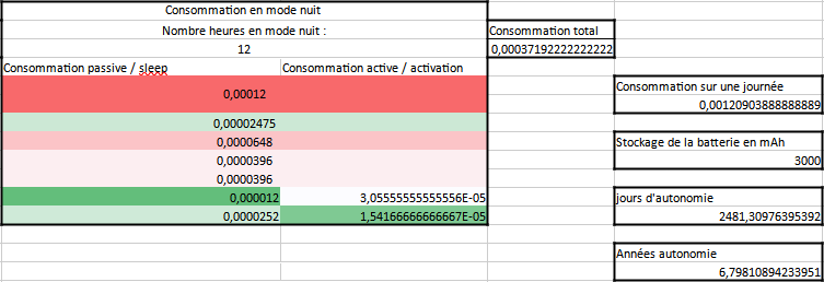
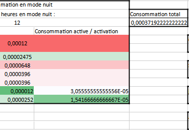
Consumption Estimate V2
We redid a consumption estimate for End Device mode and Router mode. You can find these calculations in the document "Devis_consommation" (Consumption_Estimate).
We realized that Zigbee in End Device mode can last up to 12.0 years on battery.
For Router mode, the consumption is not written in the microcontroller's datasheet. We will therefore estimate that the microcontroller consumes 10 times more and wakes up 10 times during the night. With these calculations, we arrive at an autonomy of 3.4 years.
Given the savings that the Zigbee solution brings, this solution is still attractive. An alternative with end devices connected directly to the mains (AC power) is conceivable.
Following the Component Study
After research, it will be complicated to have a functional PCB for the week of May 13th to 17th.
We do not have a (reflow) oven available for a while, which makes soldering the ESP32 mini impossible.
We can order pre-soldered PCBs, but the cost will be far too high (especially since I need several prototypes to create a network). Instead, we will propose a prototype on a "Protoboard" (perfboard/breadboard) using devkits, which have through-hole pins. Then, we will propose a final version with a PCB.
For the initial tests, we will first get the AHT20 temperature sensors working with the ESP32 C6 M1 on the protoboards.
Prototype Implementation
We start by testing the ESP32 C6 devkits. To do this, we program them with VS Code and the ESP-IDF extension. We first test a simple 'blink' program. Then, we try to program the AHT20 temperature and humidity sensor using the official library from the manufacturer, Adafruit.
The AHT20 library is not compatible with ESP-IDF, as it uses the Arduino.h and Wire.h libraries. We therefore decide to use the Arduino IDE. However, the ESP C6 chip is too recent, and it is not programmable with the Arduino IDE.
Another solution is to import these libraries with the VS Code extension Platform.io, but there are numerous errors when selecting the board, likely due to it being too new. We must recreate the AHT20 sensor library in ESP-IDF.
I started from the base of the official Adafruit library, and after several hours of programming, I cannot communicate correctly with the microcontroller. The reading of the sensor's controlWord is not correct. I then wonder if the sensor is dead (HS). I am sure the wiring itself is correct.
To verify if the sensor works, I get an Arduino Nano V3 and connect the sensor to it. I import the Adafruit library and flash the default program. On the serial connection, I then get error messages indicating that the communication failed.
I try downloading another library found on GitHub, and this time the sensor gives me the correct values. I therefore change the base library for programming. I notice that this library sends different messages for initialization.
I then manage to get the controlWord working. The biggest problem I encountered was the definition of SCL and SDA, which is done in the project's menuconfig. I finally created the functions to send the request and receive the sensor information.
After verifying that I am receiving the correct values from the sensor, I reorganize the program to make it clearer and create a GetTemperature() and GetHumidity() function. These functions manage sending the request, receiving the data, and decoding the information.
Zigbee Transmission to Home Assistant
The next step is sending the information via Zigbee.
I am starting from an existing program that transmits information from a temperature sensor, a humidity sensor, the state of a button, and receives the state of an LED. The temperature and humidity sensor in the git project is not the same as the one I am using. I am therefore modifying the sensor library and replacing the sensor functions from the git project with my own.
On the Raspberry Pi and Home Assistant side, the Zigbee coordinator is detected correctly and is not complicated to install.
After correcting 2-3 cross-cutting bugs, the ESP32 is recognized by Home Assistant.
It is possible for the ESP32 to encounter a Zigbee stack initialization error. In this case, it is necessary to erase the ESP32's flash and resend the program. This error is caused by residual data from the previous program that was not correctly erased during the new flash.
However, the value is not updated on the Home Assistant panel; the value is only sent once during the first connection or during a reboot of the end device.
On the ESP32's terminal, the value is indeed being sent every 5 seconds. The problem, then, comes from the reception. Yet, when I look at the Home Assistant logs, I see that the values are being received by the coordinator. It's Home Assistant that is not updating the temperature and humidity variable values.
To correct this error, I will first reinstall a clean version of Home Assistant, because with my inexperience, I may have modified the sensor value update parameter. After resetting Home Assistant's parameters, the values still do not update.
I then decide to install the Zigbee2MQTT extension, which is an alternative to ZHA (Zigbee Home Automation), the one installed natively in Home Assistant. For Zigbee2MQTT to work, a Broker must be installed; here I will use the Mosquitto Broker.
We can then launch Zigbee2MQTT and start the device search. This time, our system is detected correctly and updates automatically.
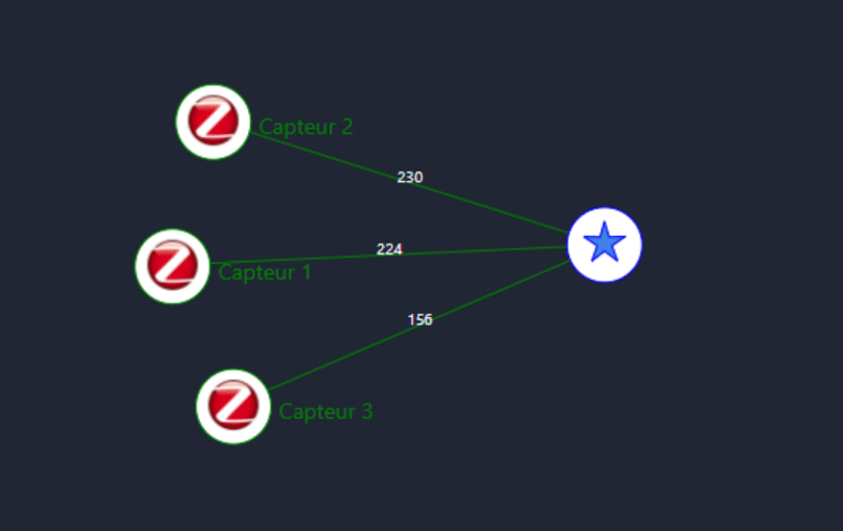
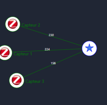
We can see here that the different systems are indeed detected and connected to the Zigbee coordinator.
Currently, the systems are all operating as "end devices," so we have a star network. Next, we need to create a mesh network. To do this, we must change the parameters of some systems so they can be defined as routers.
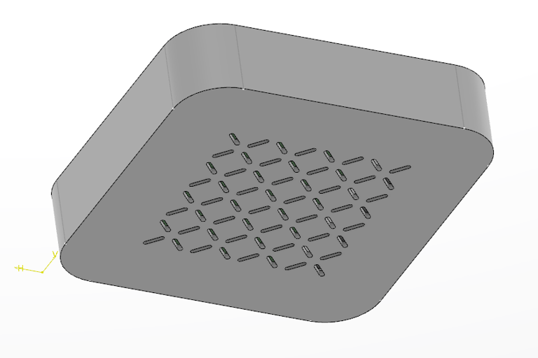
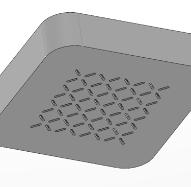
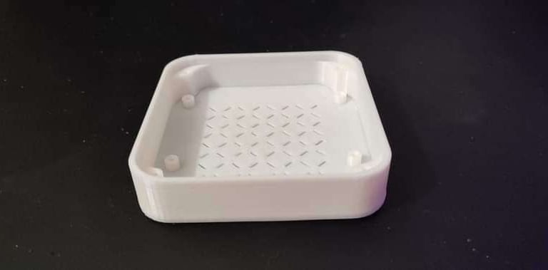
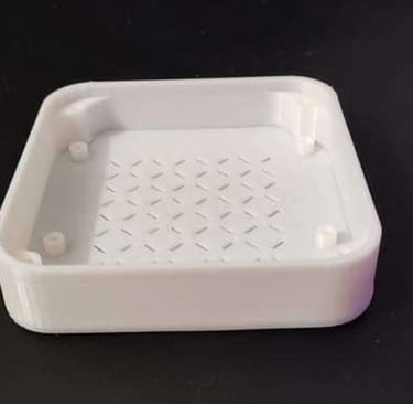
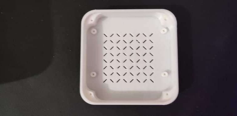
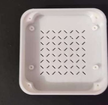
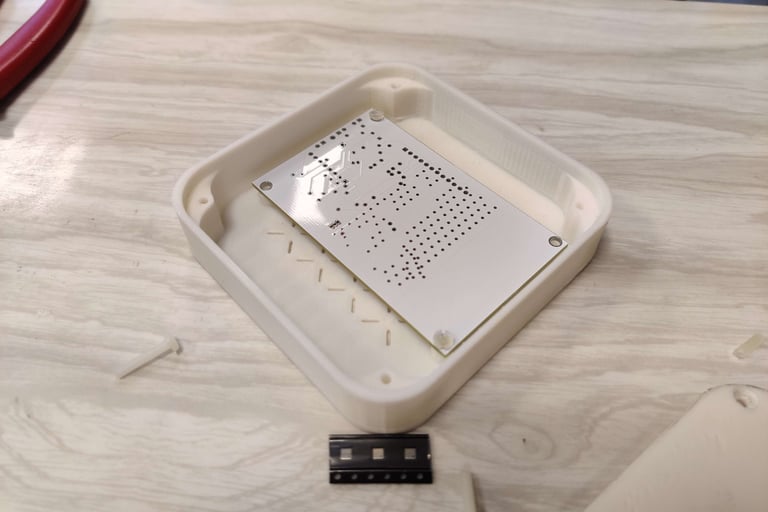
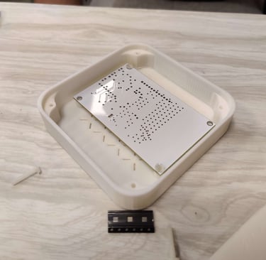
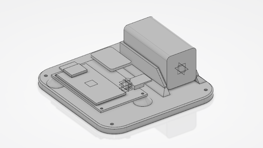
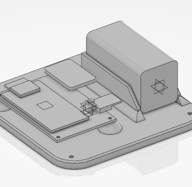
Enclosure CAD V2
A second version of the enclosure was created using the 3D Experience software. It reuses the dimensions of the [different/previous] enclosure while adapting to the new components. This model respects the rules of additive manufacturing.
This time, the components are fixed onto a plate, and a lid is added on top. This places the sensors in the direction of the openings (unlike the old model, which had the flaw of having the sensors enclosed).
PCB V2
Based on the first PCB, Kylian created a second version adapted for the ESP32 C6.
The entire [command/control] section was kept. We modified the error from the first PCB. And we placed a header to be able to program this board.
Since there is no antenna on the PCB, we were able to miniaturize this second version.
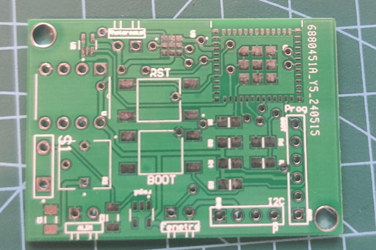
We have ordered and soldered this second version. We will subsequently test this version with the program we previously designed.
Last Project Advancement
Currently, the system is not completely finished; the following functionalities still need to be implemented:
Router Mode
Modifications still need to be made so the system can function in router mode. This should not take too long to implement.
Correct the Binary Information Send/Receive Error
The information from the window sensor switch is not reporting back to Home Assistant. The sensor information is displayed correctly in the ESP32 terminal. The error must be coming from the logical cluster, which must be misconfigured.
NTP
An NTP (Network Time Protocol) must be added to acquire the network time and calibrate to the real time.
Get the CO2 Sensor Working
The temperature and humidity sensor we tested works via I2C, just like the CO2 sensor. The program must be adapted by modifying the addresses and the messages sent so that it can communicate via I2C with the CO2 sensor.
Get the Temperature Sensor Working
The temperature sensor is not yet working. We just need to get the ADC working, then retrieve and process the value.
Get the Main Program Working
Once all the missing functions are programmed, the main program, which we previously defined in the "logic" document, must be created.
Unit Tests
System Test Battery Once the system is fully functional, it must undergo a battery of tests to ensure it properly respects each function.
Deliverables
Here are the different deliverables produced for the client at the end of the project :